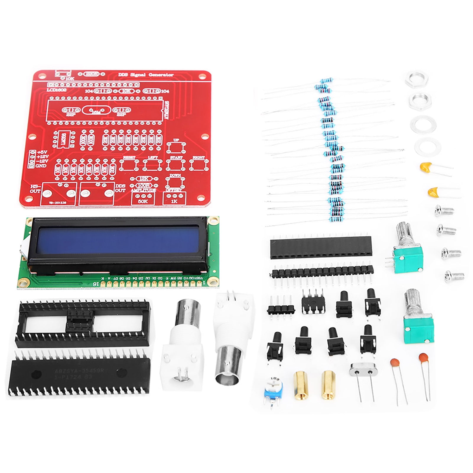
DDS Function Signal Generator Module DIY Kit Pulsed Sine Triangular Circuit Diagram DIY Function/Waveform Generator: In this project we will have a short look at commercial function/waveform generators in order to determine what features are important for a DIY version. Afterwards I will then show you how to create a simple function generator, the analog and digit…
Introduction This tutorial shows how to make a simple waveform generator by using the DAC features of the Arduino Due board. With push buttons, you will be able to choose a waveform shape (sine, triangular, sawtooth, or square) that we will send to to send to the DAC0 and DAC1 channels and change the frequency of the generated signal with a potentiometer. Goals Create a simple waveform WHAT IS THISLearn how to make a DIY frequency generator circuit using only a couple of components. RESOURCES Frequency Generator Schematic - https://drive

Arduino-Based Frequency Generator Circuit Diagram
Signal generator with ESP32. A signal generator is a fundamental instrument in electronics, used to produce waveforms of various frequencies and amplitudes. A Function generator , often known as Wave-form generator is a circuit that produces a variety of different wave-forms at a desired frequency. Function generator is one of the important devices in laboratory when it comes to generating electrical waveforms like sine, triangle,square or pulses over a range of frequencies, amplitude and duty cyle. Lets learn how to build a crude signal generator

The RF signal generator is a must to have tool when playing with radio receivers. It is used to tune a resonant circuits and adjust the gain of different RF stages. Very useful feature of the RF Signal generator is its modulation capability. If it can modulate the frequency amplitude or frequency makes it non replaceable tool for RF design works. Some time ago I have designed an AM modulator
RF Signal Generator : 8 Steps (with Pictures) Circuit Diagram
The signal generator design should include the capability to adjust signal frequency and amplitude. Moreover, devise and develop a frequency counter capable of displaying frequency of the signal being Learn how to make a square wave signal generator. With step by step instructions on how to calculate and change the frequency of the square wave.
